2015年4月30日 星期四
搭乘Uber比計程車便宜,還有優惠
我跟您介紹過 Uber App 了嗎?
嗨,我最近在使用 Uber 而且覺得服務很棒,想說你可能也會喜歡!只要使用我的優惠代碼,就能獲得首次搭乘的 400 折扣優惠,趕快到 https://www.uber.com/invite/32fiaue 註冊吧!
2015年4月22日 星期三
Raspberry Pi 入門資料
缺省帐号和密码是root/root
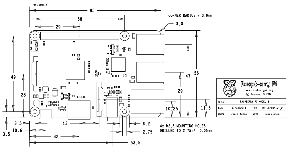
The Raspberry Pi is a series of credit card-sized single-board computers developed in the UK by the Raspberry Pi Foundation with the intention of promoting the teaching of basic computer science in schools.

Rasberry Pi Model B+

Rasberry Pi 2 Model B


https://superpiboy.wordpress.com/2014/07/20/super-pi-boy-build/

https://sites.google.com/site/raspberypishare0918/home/gpio/model-b-40pin
http://www.element14.com/community/docs/DOC-73950/l/raspberry-pi-2-model-b-gpio-40-pin-block-pinout
raspberry pi schematic
Arduino TRE 資料收集
官網 : http://www.arduino.cc/en/Main/ArduinoBoardTre
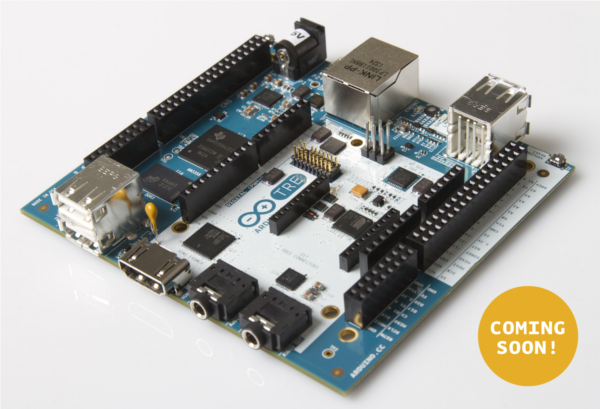
Arduino TRE, the first Arduino board manufactured in the U.S.
Thanks to the 1-GHz Sitara AM335x processor, Arduino developers get up to 100 times more performance with the Sitara-processor-based TRE than they do on the Arduino Leonardo or Uno. This performance opens the doors to more advanced Linux-powered applications. The Sitara-processor-based Linux Arduino can run high-performance desktop applications, processing-intensive algorithms or high-speed communications.
The Arduino TRE is a Sitara-processor-based Linux Arduino plus a full AVR-based Arduino, while leveraging the simplicity of the Arduino software experience. The integration of the AVR Arduino enables the Arduino TRE to use the existing shield ecosystem so that innovators can expand the Arduino TRE to develop a wide range of high-performance applications such as 3D printers, gateways for building automation and lighting automation, telemetry hubs that collect data from nearby sensors wirelessly, and other connected applications that require host control plus real-time operations.
Technical Specifications (preliminary)
| Microcontroller | Atmel ATmega32u4 |
| Clock Speed | 16 MHz |
| Flash Memory | 32 KB (ATmega32u4) |
| SRAM | 2.5 KB (ATmega32u4) |
| EEPROM | 1 KB (ATmega32u4) |
| Digital I/O Pins (5V logic) | 14 |
| PWM Channels (5V logic) | 7 |
| Analog Input Channels | 6 (plus 6 multiplexed on 6 digital pins) |
| Processor | Texas Instrument Sitara AM3359AZCZ100 (ARM Cortex-A8) |
| Clock Speed | 1 GHz |
| SRAM | DDR3L 512 MB RAM |
| Networking | Ethernet 10/100 |
| USB port | 1 USB 2.0 device port, 4 USB 2.0 host ports |
| Video | HDMI (1920x1080) |
| Audio | HDMI, stereo analog audio input and output |
| Digital I/O Pins (3.3V logic) | 23 |
| PWM Channels (3.3V logic) | 4 |
| MicroSD card | |
| Support LCD expansion connector |
Arduino Zero 資料收集
官網 : http://www.arduino.cc/en/Main/ArduinoBoardZero
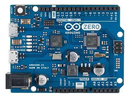
The board is powered by Atmel’sSAMD21 MCU, which features a 32-bit ARM Cortex® M0+ core.
one of its most important feature is Atmel’s Embedded Debugger (EDBG), which provides a full debug interface without the need for additional hardware, significantly increasing the ease-of-use for software debugging. EDBG also supports a virtual COM port that can be used for device programming and traditional Arduino boot loader functionality.
Summary
| Microcontroller | ATSAMD21G18, 48pins LQFP |
| Operating Voltage | 3.3V |
| Digital I/O Pins | 14, with 12 PWM and UART |
| Analog Input Pins | 6, 12-bit ADC channels |
| Analog Output Pins | 1, 10-bit DAC |
| DC Current per I/O Pin | 7 mA |
| Flash Memory | 256 KB |
| SRAM | 32 KB |
| EEPROM | up to 16KB by emulation |
| Clock Speed | 48 MHz |
2015年4月17日 星期五
GY-30 BH1750FVI 光照度傳感器
參考資料:
http://zh.wikipedia.org/wiki/%E5%8B%92%E5%85%8B%E6%96%AF
https://www.youtube.com/watch?v=sSZ_Rk8nNZQ
(GY-30) and an Arduino Uno - simtronyx - Das Elektronik Blog
關於BH1750可能的接線圖

GY-30的 ADDR接線如上圖,若空接則為LOW地址模式,地址为0x23,
若要為HIGH 地址模式地址0x5c,則可接VCC

採用ROHM原裝BH1750FVI芯片
供電電源 :3-5v
光照度範圍:0-65535 lx
傳感器內置16bitAD轉換器
直接數字輸出,省略複雜的計算,省略標定
不區分環境光源
接近於視覺靈敏度的分光特性
可對廣泛的亮度進行1勒克斯的高精度測定
有關知識
背景
1967年法國第十三屆國際計量大會規定了以 坎德拉、坎德拉/平方米、流明、勒克斯分別作為發光強度、光亮度、光通量和光照度等的單位,為統一工程技術中使用的光學度量單位有重要意義。為使您了解和使用便利,以下將有關知識做一簡單介紹:
1.candela的定義
1. 燭光、國際燭光、坎德拉(candela)的定義
在每平方米101325牛頓的標准大氣壓下,面積等於1/60平方厘米的絕對“黑體”(即能夠吸收全部外來光線而毫無反射的理想物體),在純鉑(Pt)凝固溫度(約2042K獲1769℃)時,沿垂直方向的發光強度為1 坎德拉。並且,燭光、國際燭光、坎德拉 三個概念是有區別的,不宜等同。從數量上看,60 坎德拉等於58.8國際燭光,亥夫納燈的1燭光等於0.885國際燭光或0.919坎德拉。
2. 發光強度與光亮度
發光強度簡稱光強,國際單位是candela(坎德拉)簡寫cd。Lcd是指光源在指定方向的單位立體角內發出的光通量。光源輻射是均勻時,則光強為I=F/Ω,Ω為立體角,單位為球面度(sr),F為光通量,單位是流明,對於點光源由I=F/4 。光亮度是表示發光面明亮程度的,指發光表面在指定方向的發光強度與垂直且指定方向的發光面的面積之比,單位是坎德拉/平方米。對於一個漫散射面,盡管各個方向?墓餷亢凸饌坎煌鞲齜較虻牧煉榷際竅嗟鵲摹5縭踴撓餛輛褪牆樸謖庋穆⑸涿媯源癰鞲齜較蟶瞎劭賜枷瘢加邢嗤牧煉雀小?
以下是部分光源的亮度值:單位cd/m²
太陽:1.5*10 ;日光燈:(5—10)*10³;月光(滿月):2.5*10³;黑白電視機熒光屏:120左右;彩色電視機熒光屏:80左右。
3. 光通量與流明
光源所發出的光能是向所有方向輻射的,對於在單位時間里通過某一面積的光能,稱為通過這一面積的輻射能通量。各色光的頻率不同,眼睛對各色光的敏感度也有所不同,即使各色光的輻射能通量相等,在視覺上並不能產生相同的明亮程度,在各色光中,黃、綠色光能激起最大的明亮感覺。如果用綠色光作水准,令它的光通量等於輻射能通量,則對其它色光來說,激起明亮感覺的本領比綠色光為小,光通量也小於輻射能通量。光通量的單位是流明,是英文lumen的音譯,簡寫為lm。絕對黑體在鉑的凝固溫度下,從5.305*10³cm²面積上輻射出來的光通量為1lm。為表明光強和光通量的關系,發光強度為1坎德拉的點光源在單位立體角(1球面度)內發出的光通量為1流明。一只40W的日光燈輸出的光通量大約是2100流明。
4. 光照度與勒克斯
光照度可用照度計直接測量。光照度的單位是勒克斯,是英文lux的音譯,也可寫為lx。被光均勻照射的物體,在1平方米面積上得到的光通量是1流明時,它的照度是1勒克斯。有時為了充分利用光源,常在光源上附加一個反射裝置,使得某些方向能夠得到比較多的光通量,以增加這一被照面上的照度。例如汽車前燈、手電筒、攝影燈等。
以下是各種環境照度值:單位lux
黑夜:0.001—0.02;月夜:0.02—0.3;陰天室內:5—50;陰天室外:50—500;晴天室內:100—1000;夏季中午太陽光下的照度:約為10*6次方;閱讀書刊時所需的照度:50—60;家用攝像機標准照度:1400
2015年4月14日 星期二
Apple Watch 資料收集
https://www.apple.com/tw/watch/
Apple Watch - Wikipedia, the free encyclopedia
http://en.wikipedia.org/wiki/Watch_OS
隱私問題
由於Apple Watch發表的前一週,蘋果公司的iCloud系統爆發出名人照片泄露事件,使的蘋果產品使用者的隱私權遂成為一個議題。Apple Watch能監控佩帶者的身體狀況及定位,也因此引發隱私洩露的疑慮[14]。
電池續航力問題
根據蘋果公司庫克在發表會宣稱,蘋果手錶將能持續18小時的電力。 根據蘋果公司發言人Natalie Kerris,電池續航力無法超過一天,每天都必須充電[15]。
價格高昂問題
最便宜的Apple Watch版本價格亦比同期其他品牌智能手錶高至少數百港幣。 另外,Apple Watch Edition是由18K金和藍寶石打造,因此價格高達一萬美金,媲美經典名牌的價格如勞力士等,因此成為此手錶一大爭議。 其次,Apple Watch Edition香港免稅,因此香港售賣的Apple Watch Edition比中國售賣的Apple Watch Edition便宜約兩萬港幣(約21500人民幣)。 最後,Apple Watch Edition價格高昂令人爭論蘋果品牌是否脫離實用、耐用、物有所值等的核心價值。
獨立使用問題
Apple Watch建基於iPhone之上,意即Apple Watch必須與iPhone一併使用才能完美地演繹Apple Watch的所有功能。 與此同時,蘋果發布IOS 8.2版本中,強制令iPhone用戶內置「Apple Watch」的應用程式,此舉造成部分用家不滿。
山寨手錶問題
在Apple發表智能手錶不久,淘寶網就有人開始販售仿Apple Watch外型的android手錶,馬上就有台灣立委從網上買到,並以此到議事台上質詢官員。
Dialog DA14580


http://www.dialog-semiconductor.com/docs/site-pdf/da14580_ds_v3-1.pdf
http://item.taobao.com/item.htm?spm=a230r.1.14.20.uG1HFg&id=42197045529&ns=1&abbucket=5#detail
http://item.taobao.com/item.htm?spm=2013.1.20141002.6.T3uHBU&scm=1007.10009.3949.i42197045529&id=41617638359&pvid=9b4e121c-d466-48e5-a86c-f9064f4dd0cd
參考 : 小米手环的创意- 工科男改变世界- 博客频道- CSDN.NET
小米手环的特点在于低成本和低功耗,硬件产品的两大绝对优势都被占据了,仔细分析小米手环的硬件,可见其选材充分体现了成本和功耗的辩证权衡。
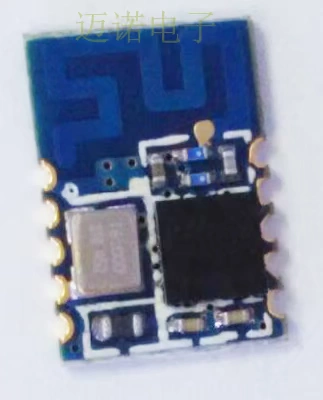
蓝牙芯片选用Dialog的DA14580芯片,经调研,该芯片的标称功耗在业界是最低的,并且和其他蓝牙芯片的标称不是一个数量级,除了低功耗之外,还有一个最大的优点是DA14580芯片内部集成了balun电路,信号单端输出,直接连上天线就可以了,撇开成本不说,在空间上就能节省很多,所以小米手环可以在一块8mm*32mm的板子上布开那么多的器件。
G-Sensor选用ADI的ADXL362芯片,该芯片的功耗在业界同样也是最低的,待机功耗仅在nA级,同时该芯片还带有主动IO功能,可以控制MOS通断,进而控制其他电路的上掉电。
DC-DC选用的TI的TPS62736,低功耗。
从以上三个主要器件的选型来看,小米手环设计的第一定位肯定是低功耗,除了增加绝对使用时间外,我想还有一个原因就是因为小米手环选用了小体积的锂电池,容量仅为41mAh。
另外值得一提的是小米手环的充电线设计,手环的充电线路设计从来是不循规蹈矩的使用microUSB,小米手环只取出USB的两个电源触点还是别出心裁的。
小米手环的腕带使用材料是硅基热塑性硫化胶。
2.4GHz 主動Balun 電路之設計與製作 - 南開科技大學機械 ...
http://www.dssz.com/2514827.html
http://wireless.murata.com/RFM/data/lbca2hnzyz-711.pdf
eTron EJ988/EJ898/ET179V
EJ898 (USB PD 2.0),
EJ179V (USB Type-C Switch with Integrated Logic Control)
EJ988 = USB PD 2.0 + USB Type-C Switch with Integrated Logic Control
針對國際USB-IF協會全力推動此等更新變革,鈺創於CES展中推出一系列IC產品,包括USB PD 2.0之EJ898、USB Type-C Switch 整合邏輯控制功能之EJ179V以及全球第1顆IC集成USB Type-C Switch加PD 2.0多功能之EJ988。
鈺創推出USB PD 2.0控制IC-EJ898,USB PD乃從電壓、電流到傳輸溝通方式,提供功率傳送之新規格進化,從USB PD 1.0提供Type-A、Type-B之功率傳輸演進至PD 2.0可提供USB Type-C連接器之需求。
EJ898其最高傳輸電力可高達100瓦,即透過20伏電壓提供5安培電流,進行供電端 (Provider) 與受電端 (Consumer) 之間雙向導電之電源供應,
EJ898也滿足電源傳輸之高度彈性,優化電源管理機制,適用於USB 3.1、USB 3.0、USB 2.0介面及其它USB規格,可廣泛應用於各類電子系統產品之具備充電功能。
為滿足手機及平板等行動裝置之電力供應需求,EJ179S可以在5伏電壓上提供電流至3安培,即15瓦之傳輸電力,並且各裝置可共用插頭,將大幅提高消費者之使用便利性,避免資源重覆浪費。
為滿足部份客戶在系統產品使用空間不足,或要減少主機板正反兩面焊接,鈺創領先全球推出第一顆IC,其中集成USB Type-C Switch 加上 PD 2.0多功能之新產品:EJ988,可支援USB Type-C連接器之正反兩面插拔、可進行20伏、5安培電力輸送,最高傳輸電力可高達100瓦。
新產品EJ988提供每秒至10 Giga-Bits之超高速傳輸頻寬,也縮小元件體積,可節省主機板面積,可被廣泛使用在輕薄短小之行動、穿戴電子系統中。
2015年4月12日 星期日
Minnowboard 相關資料收集
前幾天Papa參加WinHec於Line中跟我提及“Minnowboard“,覺得有點好奇,就上網查了下資料,將查到的資料做了下記錄。
無緣參加WinHEC,也沒能拿到MinnowBoard Max, 真是有夠他媽的幹.......
不過還是要稍微了解一下這是啥東西,這樣才不會被別人呼弄了.......
在看完後,還真的覺得沒什麼,又貴又難用,沒有甚麼理由一定要用它,若花時間玩它,感覺有點浪費生命.....
無緣參加WinHEC,也沒能拿到MinnowBoard Max, 真是有夠他媽的幹.......
不過還是要稍微了解一下這是啥東西,這樣才不會被別人呼弄了.......
在看完後,還真的覺得沒什麼,又貴又難用,沒有甚麼理由一定要用它,若花時間玩它,感覺有點浪費生命.....
可運行windows 8.1及android,linux
Get Started: http://aka.ms/winhec/devboards
Support: http://aka.ms/winhec/support
Contact: WinHardwareDevBoard@nicrosoft.com
Windows
Get Started: http://aka.ms/winhec/devboards
Support: http://aka.ms/winhec/support
Contact: WinHardwareDevBoard@nicrosoft.com

为了应对竞争对手的不断冲击,英特尔发布了支持 Linux 和 Android 的单板计算机 MinnowBoard Max,售价 99 美元。该开发板在硬件上采用 1.91GHz 主频的 Atom E3845 处理器,另外它的软件是完全开源的,你可以在这里查看 适配的固件和软件 。
MinnowBoard Max 的电路图也开放了自由下载,它的图形芯片组驱动程序也采取开源政策,用户可以自行修改。MinnowBoard Max 与树莓派(Raspberry Pi)不属于直接竞争对手,前者是为那些喜欢折腾 x86 架构系统的 DIY 爱好者准备的,后者更接近于教育工具。后者的生态系统已经非常强大,不过前者也有名为 Lure 的附加组件以扩展功能。
英特尔进入单板机领域的原因大概就是他们长时间以来的缺席。目前最受欢迎的单板机树莓派采用了 Broadcomm 公司 ARM 架构的 700MHz 系统芯片,而 Minnowboard 则将英特尔的低功耗 Atom 处理器重新带到开发者面前,使英特尔在这个领域站住脚跟(至少这是他们的目标)。

TI TPS65982
參考如下連結:
http://www.ti.com/product/TPS65982/datasheet

16.0 I2C Interface
The TPS65982 has three I2C interface ports. I2C Port 1 is comprised of the I2C_SDA1,
I2C_SCL1, and I2C_INT1 pins. I2C Port 2 is comprised of the I2C_SDA2, I2C_SCL2, and
I2C_INT2 pins. These interfaces provide general status information about the TPS65982, as
well as the ability to control the TPS65982 behavior, as well as providing information about
connections detected at the USB-C receptacle and supporting communications to/from a
connected device and/or cable supporting BMC USB-PD. The third port is comprised of the
DEBUG_CTL1 and DEBUG_CTL2 pins. This third port is always a master and has no
interrupt. This port is intended to master another device that has simple control based on mode
and mux orientation. The first two ports can be a master or a slave, but the default behavior is
to be a slave. Port 1 and Port 2 are interchangeable. Each port operates the same way and
has the same access in and out of the core. An interrupt mask is set for each that determines
what events are interrupted on that given port.
http://www.ti.com/product/TPS65982/datasheet
Features
- USB Power Delivery (PD) Controller
- Mode Configuration for Provider (Host), Consumer (Device), or Consumer-Provider
- Bi-Phase Marked Encoding/Decoding (BMC)
- Physical Layer (PHY) Protocol
- Policy Manager
- Configurable at Boot and Host-Controlled
- USB Type-C Specification 1.1 Compliance
- Attach of USB Cable at Port
- Cable Orientation and Role Detection
- Assign CC and VCONN Pins
- Advertise 1.5 A or 3 A for Type-C Power
- Port Power Switch
- 5-V, 3-A Switch to VBUS for Type-C Power
- 5- to 20-V, 3-A Bidirectional Switch to or from VBUS for USB PD Power
- 5-V, 600-mA Switches for VCONN
- Over-Current Limiter, Overvoltage Protector
- Slew Rate Control
- Hard Reset Support
- Port Data Multiplexer
- USB 2.0 HS Data, UART Data, and Low Speed Endpoint
- Auxiliary and Alternate Modes (DisplayPort and Vendor-Defined Modes)
- Power Management
- Gate Control and Current Sense for External 5- to 20-V, 5-A NMOS FET Bidirectional Switch
- Power Supply from 3.3-V, 5-V, or VBUS Source
- 3.3-V LDO Output for Dead Battery Support
- BGA MicroStar Junior Package
- 0.5-mm Pitch
- Through-Hole Via Compatible for All Pins
Applications
- Notebook Computers
- Tablets and Ultrabooks
- Docking Systems
- DisplayPort and HDMI Dongles & Cables
- Charger Adapters
- USB PD Hosts, Devices, and Dual-Role Ports
- USB PD-Enabled Bus-Powered Devices
Description
The TPS65982 is a stand-alone USB Type-C & PD controller providing cable plug and orientation detection at the USB Type-C connector. Upon cable detection, the TPS65982 communicates on the CC wire using the USB Power Delivery (PD) protocol. When cable detection and USB PD negotiation are complete, the TPS65982 enables the appropriate power path and configures alternate mode settings for internal and (optional) external multiplexers.
The mixed-signal front end on the CC pins advertises 1.5 A or 3 A for Type-C power providers, detects a plug event and determines the USB Type-C cable orientation, and autonomously negotiates USB PD contracts by adhering to the specified bi-phase marked coding (BMC) and physical layer (PHY) protocol.
The port power switch can pass up to 3 A downstream at 5 V for legacy and Type-C USB power. An additional bidirectional switch path can provide USB PD power up to 3 A at a maximum of 20 V as either a provider (host), consumer (device), or provider-consumer.
The TPS65982 can also be a Downstream-Facing Port (DFP), Upstream-Facing Port (UFP), or Dual-Role Port (DRP) for data. The port data multiplexer can pass data to or from the top or bottom D+/D- signal pair at the port for USB 2.0 HS or UART and has a USB 2.0 Low Speed Endpoint. Additionally, the Sideband Use (SBU) signal pair is used for auxiliary or alternate modes of communication (DisplayPort or vendor-defined modes, for example).
The power management circuitry can utilize a 3.3-V or 5-V power supply inside the system, and also use VBUS to start up and negotiate power for a dead battery or no battery condition.
16.0 I2C Interface
The TPS65982 has three I2C interface ports. I2C Port 1 is comprised of the I2C_SDA1,
I2C_SCL1, and I2C_INT1 pins. I2C Port 2 is comprised of the I2C_SDA2, I2C_SCL2, and
I2C_INT2 pins. These interfaces provide general status information about the TPS65982, as
well as the ability to control the TPS65982 behavior, as well as providing information about
connections detected at the USB-C receptacle and supporting communications to/from a
connected device and/or cable supporting BMC USB-PD. The third port is comprised of the
DEBUG_CTL1 and DEBUG_CTL2 pins. This third port is always a master and has no
interrupt. This port is intended to master another device that has simple control based on mode
and mux orientation. The first two ports can be a master or a slave, but the default behavior is
to be a slave. Port 1 and Port 2 are interchangeable. Each port operates the same way and
has the same access in and out of the core. An interrupt mask is set for each that determines
what events are interrupted on that given port.
16.3 I2C Address Setting
SWDIO : Serial Wire Debug http://www.arm.com/zh/products/system-ip/debug-trace/coresight-soc-components/serial-wire-debug.php
2015年4月9日 星期四
NodeMCU - NTP Client
今天想到要利用NTP Server 來 Sync 時間 , 搜尋了一下,找到了這個連結 ........
ntp.lua 內容如下:
-- -----------------------------------------------------------------------------------
-- for a continuous run:
-- TIME=loadfile("ntp.lua")()
-- TIME:run(timer,updateinterval,syncinterval,[ntp-server])
-- TIME.hour TIME.minute TIME.second are updated every 'updateinterval'-seconds
-- NTP-server is queried every 'syncinterval'-seconds
--
-- a one-time run:
-- ntprun=loadfile("ntp.lua")
-- ntprun():sync(function(T) print(T:show_time()) end)
--
-- config:
-- choose a timer for udptimer
-- choose a timeout for udptimeout
--    timer-function to close connection is needed - memory leaks on unanswered sends :(
-- set tz according to your timezoneddddddd
-- choose a NTP-server near you and don't stress them with a low syncinterval :)
-- -----------------------------------------------------------------------------------

return({
    hour=0,
    minute=0,
    second=0,
    lastsync=0,
    ustamp=0,
    tz=8,
    udptimer=2,
    udptimeout=1000,
    ntpserver="193.170.62.252",
    sk=nil,
    sync=function(self,callback)
        -- print("SYNC " .. self.ustamp .. " " .. self.ntpserver)
        -- request string blindly taken from http://arduino.cc/en/Tutorial/UdpNTPClient ;)
        local request=string.char( 227, 0, 6, 236, 0,0,0,0,0,0,0,0, 49, 78, 49, 52,
        0,0,0,0,0,0,0,0,0,0,0,0,0,0,0,0,0,0,0,0,0,0,0,0,0,0,0,0,0,0,0,0
        )
        self.sk=net.createConnection(net.UDP, 0)
        self.sk:on("receive",function(sck,payload)
            -- tmr.stop(self.udptimer)
            sck:close()
            self.lastsync=self:calc_stamp(payload:sub(41,44))
            self:set_time()
            if callback and type(callback) == "function" then
                callback(self)
            end
            collectgarbage() collectgarbage()
            -- print("DONE " .. self.ustamp)
        end)
        self.sk:connect(123,self.ntpserver)
        tmr.alarm(self.udptimer,self.udptimeout,0,function() self.sk:close() end)
        self.sk:send(request)
    end,
    calc_stamp=function(self,bytes)
        local highw,loww,ntpstamp
        highw = bytes:byte(1) * 256 + bytes:byte(2)
        loww = bytes:byte(3) * 256 + bytes:byte(4)
        ntpstamp=( highw * 65536 + loww ) + ( self.tz * 3600)    -- NTP-stamp, seconds since 1.1.1900
        self.ustamp=ntpstamp - 1104494400 - 1104494400         -- UNIX-timestamp, seconds since 1.1.1970
        -- print(string.format("NTP: %u",ntpstamp))
        -- print(string.format("UIX: %u",self.ustamp))
        return(self.ustamp)
    end,
    set_time=function(self)
        self.hour = self.ustamp % 86400 / 3600
        self.minute = self.ustamp % 3600 / 60
        self.second = self.ustamp % 60
        -- print(string.format("%02u:%02u:%02u",hour,minute,second))
    end,
    show_time=function(self)
        return(string.format("%02u:%02u:%02u",self.hour,self.minute,self.second))
    end,
    run=function(self,t,uinterval,sinterval,server)
        if server then self.ntpserver = server end
        self.lastsync = sinterval * 2 * -1    -- force sync on first run
        tmr.alarm(t,uinterval * 1000,1,function()
            self.ustamp = self.ustamp + uinterval
            self:set_time()
            -- print(self:show_time())
            if self.lastsync + sinterval < self.ustamp then
                self:sync()
            end
        end)
    end
})
測試了一下,真的能用, 輸出如下:
> ntptable=loadfile("ntp.lua")()
> --調整時區設定, 在這我設成台北時間: GMT+8
> ntptable.tz=8
> --設定timerid=1 , 定時每1秒從"tock.stdtime.gov.tw"讀取NTP時間
> ntptable:run(1,1,0,"211.22.103.157")
> print(ntptable:show_time())
05:10:38
> print(ntptable:show_time())
05:11:20
or
> ntpfun=loadfile("ntp.lua")
> ntpfun():sync(function(T) print(T:show_time()) end)
> 05:15:59
ntpfun():sync(function(T) print(T:show_time()) end)
> 05:16:29
or
> ntptable=loadfile("ntp.lua")()
> ntptable:sync(function(T) print(T:show_time()) end)
> 05:15:59
ntptable:sync(function(T) print(T:show_time()) end)
> 05:16:29
註:別忘了要設時區,不然時間會有時差的....
另外,若有需要,可自行依當地時區,再進行日光節約時間校正 .....
以下為台灣國家時間與屏率標準實驗室NTP Server :
tock.stdtime.gov.tw  211.22.103.157
watch.stdtime.gov.tw  118.163.81.63
time.stdtime.gov.tw  118.163.81.61
clock.stdtime.gov.tw  211.22.103.158
tick.stdtime.gov.tw 118.163.81.62
相關參考資料:
鳥哥的Linux 私房菜-- NTP 時間伺服器
NTP 伺服器位址 - 國家時間與頻率標準實驗室
NTP - Wikipedia
夏令時間- 維基百科,自由的百科全書 - Wikipedia
訂閱:
文章 (Atom)